


Four Essential Decisions Before Installing a Time-Lapse Camera

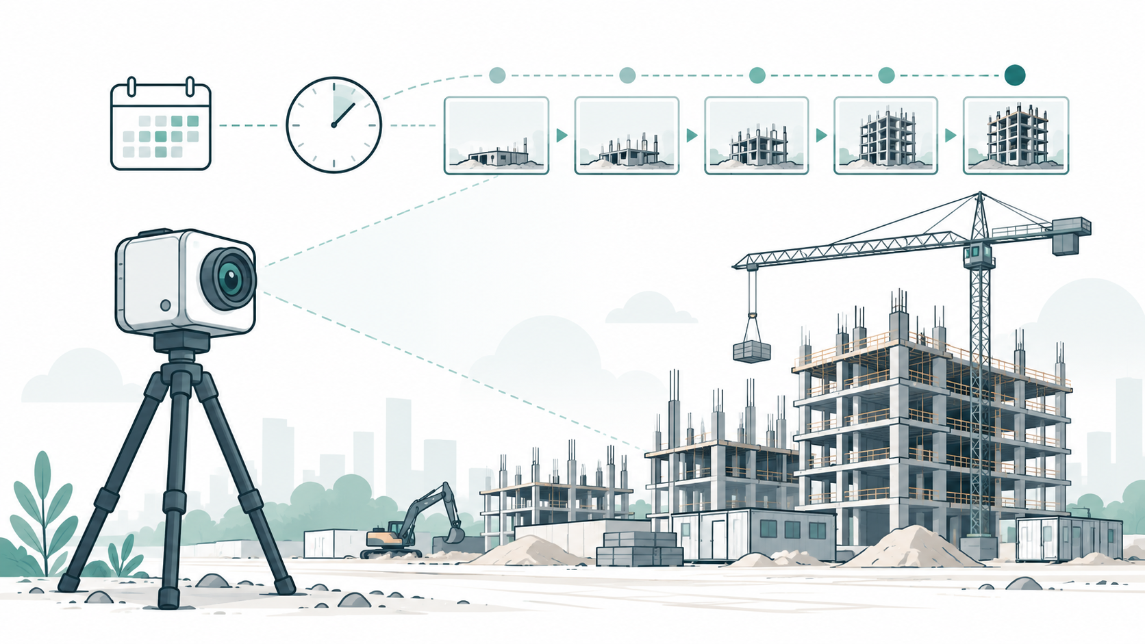
Four Essential Decisions Before Installing a Time-Lapse Camera
A Practical Guide to Planning Time-Lapse Coverage for Construction, Industrial, and Creative Projects | Trivion Tek Türkiye
A time-lapse camera may record reliably for months, yet the finished video can still fall short of the client’s expectations. Part of the structure might be hidden behind a crane, a critical operation may take place between captured frames, or an unstable mount may cause the composition to shift slightly from one image to the next. In such cases, the camera’s image quality is not necessarily the problem. The recording plan may simply not have been properly designed before installation.
A successful time-lapse project does not begin with choosing where to mount the camera. It begins by defining the desired result. Is the aim to show progress in a management report, document every stage of construction, or produce an engaging project showcase? The answer determines what must remain visible, how many viewpoints are needed, and how the system should operate throughout the project.
Before installation, make four decisions: the capture schedule; the coverage plan and number of cameras; the mounting location and site conditions; and the strategy for power, access and data management.
Lorem ipsum dolor sit amet, consectetur adipiscing elit. Ut elit tellus, luctus nec ullamcorper mattis, pulvinar dapibus leo.
1. Plan the Recording: Match the Capture Interval to the Pace of the Project
Identify the key activities first
Project duration alone is not a reliable basis for camera settings. A residential development may take two years, with little visible change during some weeks but rapid progress during steel erection or façade installation. By contrast, a public mural may be finished in four days, with noticeable changes to the scene every hour.

The capture interval is the time a camera waits between successive frames. A shorter interval records more intermediate changes but increases the frame count and generally the demand on storage and power. A longer interval simplifies long-term recording, but some fast-moving activities may be missed.
Suggested Starting Points for Capture Intervals
| Project type and objective | Initial interval to test | Reason for choosing it |
|---|---|---|
| Long-term construction; overall progress | 5–10 minutes | Captures the main progression while keeping the number of frames manageable |
| A specific phase, such as façade or structural installation | 30 seconds–2 minutes | Captures movement and finer progress |
| A mural or artwork completed over several days | 10–30 seconds | Shows continuous changes over a short period |
| Exhibition or event setup over several days | 5–30 seconds | Captures rapid assembly and repositioning |
These ranges are starting points for testing, not mandatory settings. Brinno guidance also suggests a five-minute interval for long-term construction and 10–20 seconds for mural projects. The final choice should reflect the actual pace of the scene, the equipment’s capabilities and the intended video length.
Formula: How Long Will the Raw Video Be?
With a regular recording schedule, you can estimate the raw video duration before installation:
Video duration (seconds) ≈ [active days × recording hours per day × 3,600] ÷ [capture interval (seconds) × playback frame rate (fps)]
Consider a two-year project. For this illustrative calculation, assume 520 working days, eight recording hours per day and playback at 30 frames per second:
| Capture interval | Approximate frame count | Raw video duration |
|---|---|---|
| 10 minutes | 24,960 | 13 minutes 52 seconds |
| 5 minutes | 49,920 | 27 minutes 44 seconds |
| 2 minutes | 124,800 | 69 minutes 20 seconds |
For a four-day mural recorded eight hours a day at 20-second intervals, the raw footage would be approximately 3 minutes 12 seconds at the same playback rate. These calculations describe ideal capture conditions. Interruptions, schedule changes, removed frames and editing can all change the finished duration. Raw footage length and the duration of an edited film are therefore not the same.
Working Hours and Lighting: Two Related but Distinct Settings
The schedule determines which days and hours the camera records; the interval determines how often frames are captured within those hours. On a site active only from 8 a.m. to 5 p.m., overnight recording might add thousands of frames with little value. Conversely, if concrete pours or equipment installation take place on a night shift, excluding those hours means missing part of the project’s story.
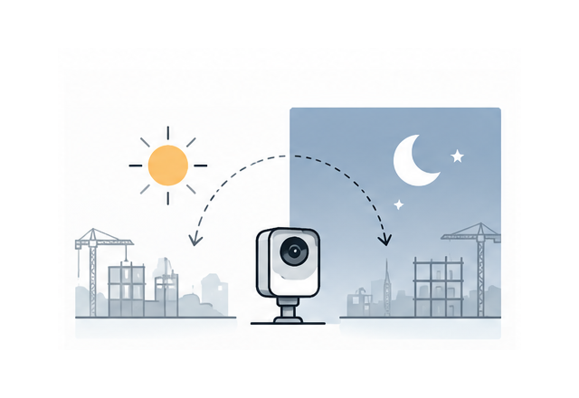
At night, having floodlights is not enough. Artificial lighting may vary in brightness or colour and, together with the camera’s exposure settings, cause frame-to-frame brightness fluctuations, or flicker. Where a scene includes both daylight and nighttime illumination, test the actual conditions and assess exposure, white balance, low-light settings and anti-flicker features where supported by the camera model. No single setting can be assumed to correct every artificial light source without testing.
Practical rule: Base the recording schedule on the activity calendar, and plan from the outset to adjust the interval temporarily during critical phases.
2. Design Camera Coverage: Is One Camera Enough, or Are Multiple Angles Needed?
Choose the number of cameras based on what the final video needs to show
Before deciding how many cameras to install, identify the parts of the project that matter in the final video. A wide view is useful for showing the gradual rise of a structure, but it may not clearly capture façade work, activity behind a building or landscaping. The site’s area is only one consideration. Clear sightlines to important operations, blind spots, distance to the subject and the level of detail required are equally important.
For example, when constructing the entrance to a university or commercial complex, one camera may document the main work area. As construction progresses, however, scaffolding, temporary structures or the building itself can obscure certain activities. If documenting those operations matters to the client, adding a complementary viewpoint is more sensible than trying to fit everything into an excessively wide shot.
Start by dividing the required shots into three groups: an overview to show overall progress, a medium view to follow a particular work zone, and a detail view for operations that cannot be clearly understood in the wide shot. Then determine whether one fixed position meets these needs or another angle is required. There is no fixed ratio between project area and the number of cameras.
From Lens Angle to What the Camera Can Actually See
Saying that a camera has a wide field of view does not tell us how much of the project will be visible from a particular installation point. Lens field of view, camera orientation and tilt, and distance to the subject are three separate factors. The lens determines the angular extent of the scene captured; direction and tilt determine where that view is aimed; and distance changes the apparent size of subjects and the dimensions of the visible area.
A camera is commonly specified by three fields of view: horizontal field of view (HFOV), spanning the frame from left to right; vertical field of view (VFOV), covering its height; and diagonal field of view (DFOV), measured from one corner to the opposite corner. A specification such as “118°” is therefore insufficient for calculating coverage unless the type of angle is identified.
For example, one Brinno specification table lists the TLC5000 camera in the BCC5000 kit with an overall field of view of 118°, a horizontal field of view of 106° and a vertical field of view of 65°. Other official information for the same product also lists 114° horizontally and 77° vertically, alongside a different stated focal length. For actual system design, confirm the specifications for the lens version and recording mode being used. The following examples use only the 106°/65° values.
1) How Wide and Tall Is the Frame at a Given Distance?
For an imaginary plane perpendicular to the camera’s optical axis, the approximate frame dimensions can be calculated using two relationships:
Here, d is the straight-line distance to that plane. At a distance of 20 metres, an HFOV of 106° and a VFOV of 65° produce an estimated geometric width of 53.1 metres and a height of 25.5 metres. Both dimensions matter: coverage is not simply “53 metres wide”; it is a two-dimensional area with a defined height.
This is a simplified geometric model for preliminary estimates, not an exact measurement of a wide-angle lens’s real image. Lens distortion, digital corrections and cropping may alter the effective dimensions. If the target is a building façade or another angled surface instead of a plane perpendicular to the optical axis, the perspective of that surface must also be considered.
2) What Changes When the Camera Is Mounted High and Tilted Down?
In this situation, width and height on an imaginary image plane are not enough. To estimate where the camera’s view begins and ends on approximately level ground, we also need the lens height above ground (h) and the downward tilt angle from the horizontal (α).
Let half the vertical field of view be β = VFOV / 2. Provided both vertical edges of the view intersect the ground, the near and far ground distances, measured horizontally from the point directly below the camera, can be approximated as follows:
3) How Do These Calculations Help Determine Camera Positions and Quantity?
Raising a camera can reduce obstructions from scaffolding or machinery and may improve visibility of areas behind the main work zone. But it also changes the area within the frame and the apparent size of details. Wider coverage does not necessarily mean more useful information. If an important activity occupies only a tiny part of the frame, even 4K footage may fail to show the required detail.
To plan coverage, first mark the approximate distance and mounting height on a site plan. Then use the actual lens version’s HFOV and VFOV to estimate the initial frame boundaries. Check the proposed position with test images: will key activities remain visible throughout construction, where are the blind spots, and are the necessary details large enough in the frame? If one location cannot provide both an overview and coverage of essential operations, use a complementary angle rather than estimating camera count from site area alone.
Technical note: These formulas provide preliminary estimates for a rectilinear lens model and idealised surfaces. On sloping ground, with structures at different depths, lens distortion, obstructions or cropping, the actual frame must be verified through an on-site test.
Diagram 2 — One Overview and One Complementary Camera Angle
Camera C1 covers the main overview. Camera C2 can capture areas obscured from the first viewpoint. This is a conceptual example, not a rule for determining camera quantity.
Practical tip: Before permanent installation, take a test photograph from each proposed position and mark areas that cannot be seen on the site plan. Moving a camera a few metres away from a poor position can sometimes be more effective than adding another camera.
3. Installation Location and Site Conditions: Keeping the Camera Stable for Months
A Real-World Challenge: The Camera Recorded, but the Frame Would Not Stay Still
In a project whose time-lapse footage we reviewed, the camera was installed at an elevated location to capture an overview of site activities. The viewing angle initially appeared suitable. The real problem was insufficient rigidity in the supporting structure and camera mount. The images and framing were not checked periodically during recording.
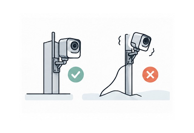
The camera continued recording and the images were captured. The problem only became apparent after recording had ended, when the images were assembled into the final video: the framing shifted noticeably in parts of the footage, causing subjects to jump across the screen instead of moving naturally as construction progressed. In time-lapse production, this is known as frame jitter or frame instability.
A crucial distinction is that a single photograph can appear sharp and acceptable while the sequence produces an unstable video. A time-lapse camera must observe the scene from an almost fixed reference point. If its mount is not rigid enough, small changes in position accumulate across successive frames and become much more obvious during fast playback. Sensor quality and high resolution cannot compensate for an unstable mounting system.
The experience highlighted a key lesson: the end of the recording period is too late for the first quality check. Comparing early frames might have revealed the problem and allowed the mount or camera position to be corrected before recording continued. Digital stabilisation during editing can sometimes reduce visible jitter, but it may require cropping and reduce the usable field of view. No method can be guaranteed to undo every consequence of poor installation.
Prevention involves more than tightening the camera screw. The support structure, connections, extension arms and attachment point to the main structure must all be assessed. A mount attached to a vibrating railing, flexible pole or temporary structure may remain unstable even when the camera itself appears firmly secured. Exposure to people and machinery, wind loads and safe maintenance access should also influence location selection.
A practical approach is to record a few hours or one full trial day after installation, compare the resulting frames, and reassess the mount and composition after several days or significant environmental changes. For long-term projects, inspection frequency should reflect wind exposure, the support structure and site accessibility. This helps prevent a minor fault from becoming a problem discovered only at project completion.
Assess Sunlight Throughout the Day and Across Seasons
An angle that provides balanced exposure at 10 a.m. may produce direct glare, strong reflections from glazing or backlit subjects later in the day. On multi-month projects, the sun’s path and day length also change with the seasons. Rather than applying one universal mounting direction, align camera orientation with the site’s actual recording hours and lighting conditions.
Before final installation, take sample images at different times of day. Consider neighbouring buildings’ shadows, reflections from metal and glass, crane movements and the increasing height of the structure.
Temperature, Rain and Dust: A Protective Housing Does Not Solve Everything
For outdoor installation, assess three separate factors: the camera’s operating temperature range, the housing’s ingress protection rating and the actual conditions at the mounting point. Ambient air temperature may differ from the temperature inside an enclosure exposed to direct sunlight. Likewise, an ingress protection rating does not guarantee unrestricted operation in extreme heat or cold.
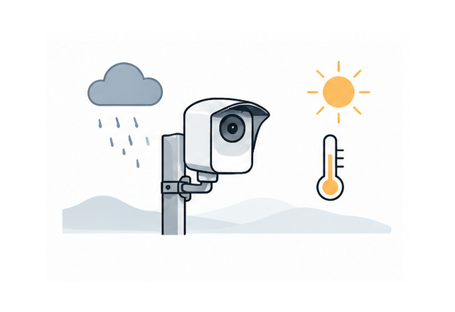
For example, the Brinno BCC5000 kit includes the TLC5000 4K camera, ATH5000 housing and ACC5000 mount. The kit’s official specifications list IP65 protection for the ATH5000 housing and a camera operating temperature range of 0–45°C. Because some Brinno support pages provide different temperature figures, projects in challenging climates should verify the exact product revision and manufacturer recommendations before installation.
In humid locations, proper sealing and compatible desiccants can help limit condensation inside the housing. Connections, enclosures and accessories should also be checked during scheduled inspections.
4. Power, Access and Data: Plan for the Day After Installation
The Power System Must Last as Long as the Recording Plan Requires
Battery life depends on capture interval, recording hours, temperature, battery condition and how connectivity features are used. On a project lasting more than a year, do not confuse the advertised battery life with the maintenance interval your project requires. Establish from the beginning who will check the camera, how often and under what access arrangements.
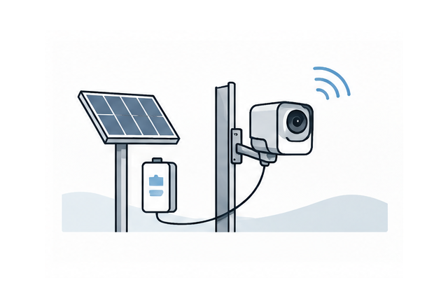
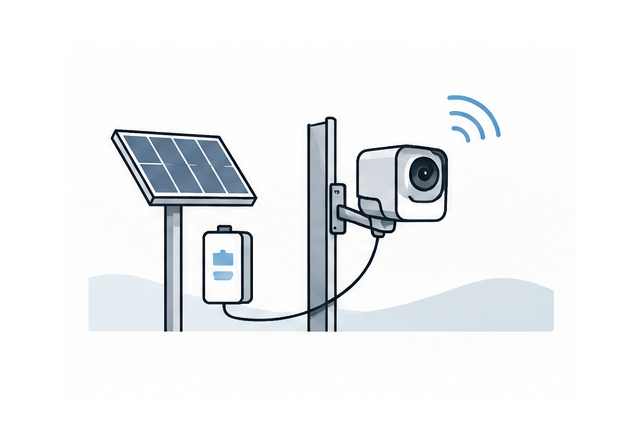
Solar power can be useful where mains electricity is limited, but performance depends on panel location, future shading, seasonal sunlight, camera consumption and energy storage capacity. Brinno offers the ASP1000-P solar kit for compatible BCC5000 systems. Choose such equipment based on actual site conditions, not an assumption of guaranteed power on every day of the year.
Access to the Camera Is Part of Installation Design
Imagine having to rent an aerial lift or stop part of the construction site every time you need to retrieve the memory card. Even if the camera works perfectly, that servicing approach was poorly planned from the start. The installation point should be both safe and reasonably accessible where possible. If physical access is difficult, decide on control and file-retrieval methods before installing the equipment.
BCC5000 supports Bluetooth for local setup and configuration, as well as 2.4 GHz Wi-Fi for network connectivity and supported remote-management features. This distinction matters: Bluetooth is not an internet connection, and Wi-Fi does not mean the camera has a built-in SIM card or cellular data. Off-site access depends on network infrastructure, reliable connectivity and correct service configuration. The camera can continue recording to its memory card without Wi-Fi, but remote control and retrieval features will not be available.
Estimate Storage Needs Using Actual File Sizes
The TLC5000 supports microSD cards up to 256 GB. Capacity alone, however, does not tell you how many months of recording will fit. Resolution, compression, capture settings and actual file sizes all matter. Run a short on-site trial, measure the generated files and extrapolate from the project’s expected duration. Never rely on the memory card as the only copy of project footage.
Before main recording begins, assign responsibilities: Who checks camera operation? When are backups taken? Who responds if recording stops or the camera’s view is obstructed? A one- or two-day trial is also advisable to check framing, lighting, settings, storage and power.
Before You Press Record
- The final video objective and key project activities are clearly defined.
- The capture interval and recording hours have been tested with a short sample.
- Camera coverage, blind spots and future site changes have been reviewed.
- Mounting height, distance, orientation and tilt have been assessed separately.
- The support has been checked for vibration, wind exposure, security and safe access.
- Morning and afternoon lighting, and artificial night lighting if applicable, have been tested.
- Power, storage, network connectivity and backup arrangements are defined.
- An initial test period and a responsible maintenance contact have been assigned.
Conclusion: A Successful Time-Lapse Video Starts with Proper Planning
A successful construction time-lapse project is not simply about capturing images over several months. The real objective is to produce a final video that clearly and consistently documents the key stages of construction progress from a carefully selected perspective.
Choosing the right capture interval, determining the optimal camera position, ensuring a secure and stable mounting system, and establishing a regular equipment inspection schedule all play an essential role in achieving reliable results.
Overlooking any of these factors can compromise the final video. Even high-resolution footage may fail to provide clear and useful project documentation if camera positioning, recording settings, or mounting stability are not properly considered.
Learn from a Real Construction Time-Lapse Project
To better understand how these factors influence real-world results, explore our case study:
This case study examines how capture intervals, camera placement, and mounting stability affect construction time-lapse footage. It also highlights the consequences of insufficient mounting stability and the importance of periodic monitoring throughout the recording period.
Find the Right Time-Lapse Solution for Your Project
Every construction project has different requirements depending on its duration, working hours, environmental conditions, power availability, connectivity, and documentation objectives.
At OPTIX Security & Equipment L.L.C., based in Dubai, UAE, we provide Brinno construction time-lapse cameras, compatible accessories, and project-specific monitoring solutions for contractors, developers, and project management teams.
Our solutions include camera selection, mounting accessories, power supply options, and connectivity planning. We also provide installation, technical support, and time-lapse video editing services to support project documentation requirements.
Whether you are documenting a long-term construction project, monitoring a specific construction phase, or preparing a final progress video for stakeholders, our team can help you identify a suitable solution.
Share your project duration, working hours, installation environment, available power and internet connections, and expectations for the final video. Based on these details, we can recommend an appropriate camera setup and supporting equipment.
Contact OPTIX UAE
Email: info@optixllc.ae
Phone: +971 50 464 3542
WhatsApp:
Office Address: Office US-036, S2 Floor, Burjuman Business Tower, Bin Zayed Road, Al Mankhool, Dubai, UAE.